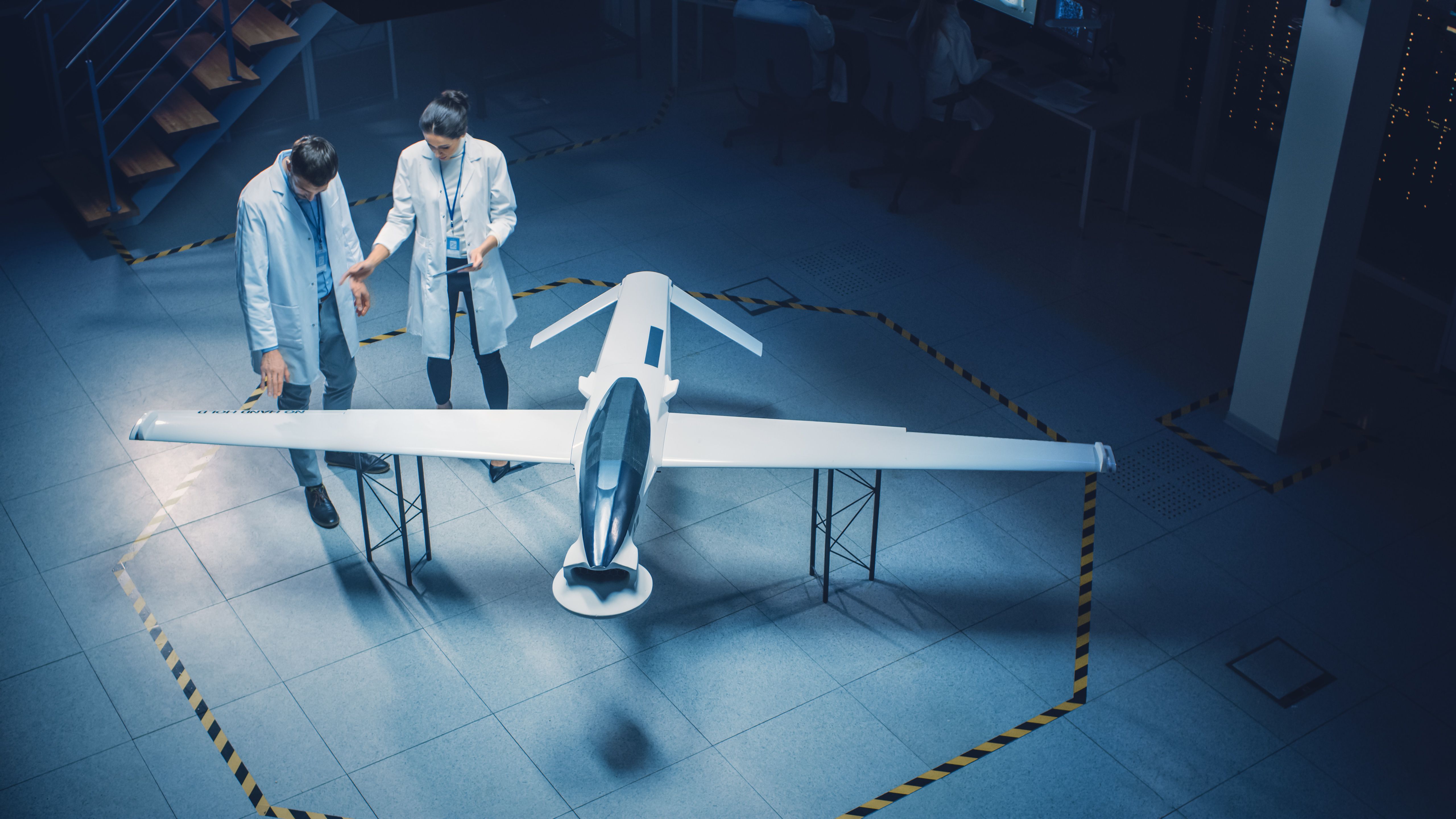
The conceptual design considers aircraft aerodynamics, propulsion systems, performance constraints, structure, and control systems. The shape of the aircraft and the location of major components, such as wings, stabilizers, and power plants, are determined.
Concept development
Specialized design tools are required to develop the conceptual design. The aircraft development tool is used to create conceptual sketches of the aircraft. Illustrations with various configurations are made in the first iteration. The first iteration of sizing takes place with the dimensions and ratios of the main components of the aircraft.
For example, the fuselage width-to-length ratio, the size, and placement of the engines, the type of tail section used, the size and location of the wings, and the height of the landing gears. The first geometrical design is fed into the Computational Fluid Dynamics (CFD) tools for load and aerodynamic fluid flow analysis.
The sizing of main components and various systems are validated using the software. The first version data package includes structural weight, engine thrust, bleed air requirements, hydraulics, and electrical supply for the aircraft.
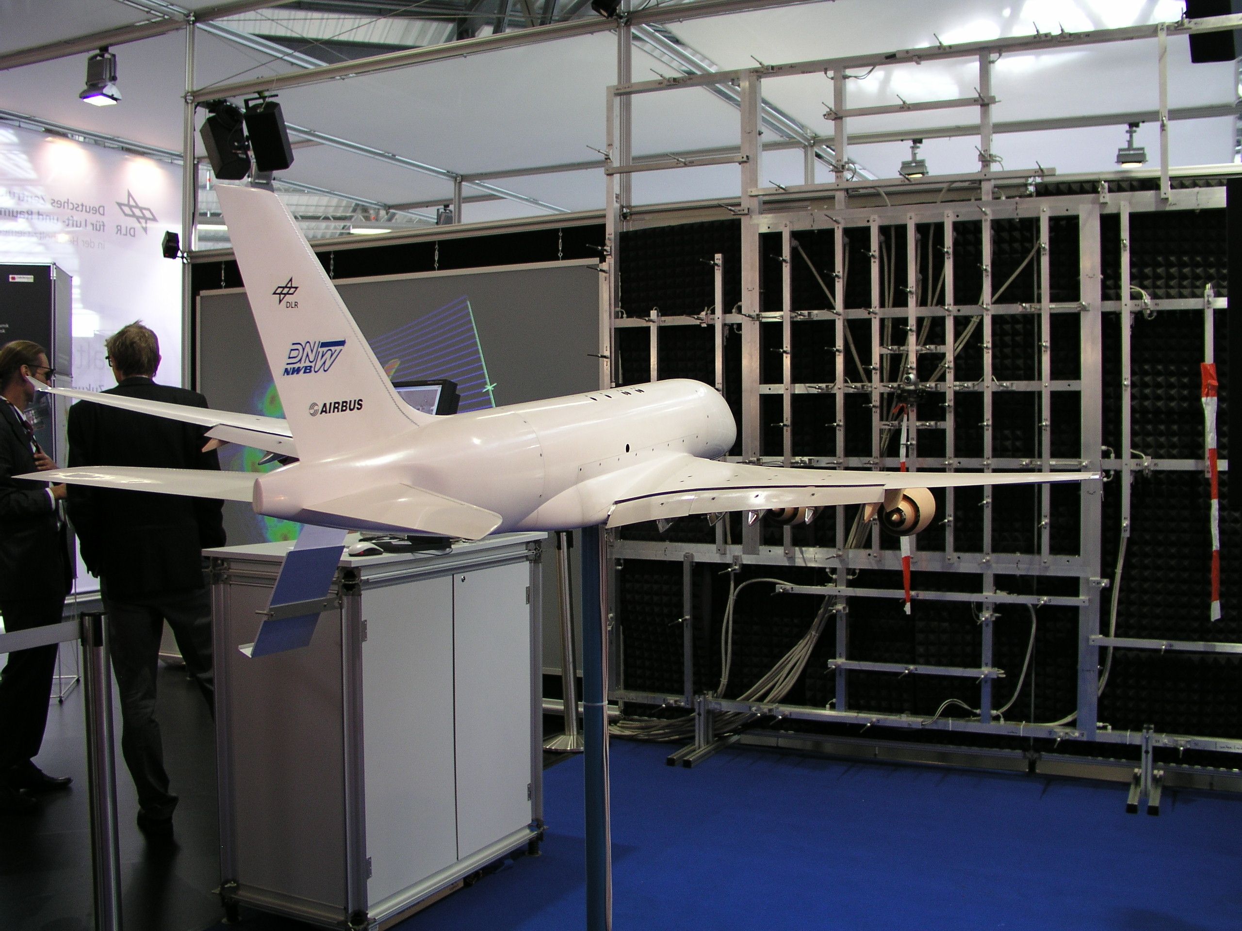
While most high-speed (cruise) conditions are tested using CFD tools, low-speed aerodynamics are performed in a wind tunnel. A scaled model is typically built to run wind tunnel experiments to obtain takeoff and landing data, including speeds, pressures, and aerodynamic forces (lift, drag, and moments).
The conceptual design is discussed with the customers during their visits. It is common for large manufacturers like Boeing and Airbus to work closely with their special customers during the initial phases of design.
Refining the concept
Based on the analysis from the first iteration and customer feedback, shapes, dimensions, and locations of major components are finalized. The aircraft control surfaces on wing and tail sections are refined to support the overall design. A larger-scaled model with an updated shape and configuration is manufactured for wind tunnel testing. Manufacturers may opt for a 1:5 scale half-model at this stage.
Various wing configurations are tested for the flight take-off, climb, and landing phases. High-speed cruise conditions are retested using the CFD tool with the updated design. The data is fed into the design database, where stress analysis on all aircraft parts is performed. Various aerodynamic load conditions are considered during stress analysis.
For example, high bank angle loads, severe turbulent loads, horizontal and vertical gust loads, and hard landing loads. Engine flame-out loads are also tested to prepare the design for safe operations during emergency situations.
Functional Hazard Analysis (FHA)
Structural concepts for material fatigue, flutter, and inflight variance are incorporated into the design. The data from the wind tunnel analysis is also used for Functional Hazard Analysis (FHA). The FHA comprises the deployment of specific secondary systems if the primary systems fail.
For example, the emergency deployment of the ram-air turbine (RAT) and its effects on systems’ design and functionality. The first iteration of the FHA analysis aids in discussions with the regulatory authorities about design certification.
The revised design is ready for supplier selection and collaboration for parts. It is noteworthy that minor changes to the final design may still occur in the following phases. However, the sizing and location of the major components and systems of the aircraft are finalized.
What do you think about the key steps in aircraft concept development? Tell us in the comments section.


